Structural Drawings
Designing Strength and Resilience:
The Principles of Structural Engineering
Code Compliant
Drawings
Fast Turnaround
Time
USA Buildings
Code Standards
Permit-Ready
Packages
At Noblyn LLC, we deliver precise, permit-ready structural drawings and accurate load calculations that transform architectural concepts into safe, buildable structures. Every structural drawing package we produce is engineered to meet IBC, IRC, and jurisdiction-specific code requirements — providing building departments, contractors, and project owners with the structural confidence they need to move from permit submission to construction without delays.
Structural integrity is not negotiable. A poorly engineered or incomplete structural drawing set puts lives at risk, delays permits, and creates costly problems on site. At Noblyn, our structural drawings are produced by experienced engineers who understand both the science of load paths and the practical demands of real-world construction. We analyse dead loads, live loads, wind loads, and site-specific conditions to design structures that perform safely under every scenario — and we document every calculation and design decision in a comprehensive structural package that satisfies even the most rigorous plan reviewers.
Benefits
- IBC & IRC code-compliant drawings
- Complete load calculations included
- Foundation , framing & connections
- Coordinated with architectural plans
- Wind , seismic & snow load analysis
- Shear wall & lateral system design
- Serving clients across the globe
Perfect Planning — Structural Engineering That Builds With Confidence
Approach
We begin every structural project with a detailed review of your architectural drawings, site conditions, and local code requirements. Our engineers then design the structural system from the ground up — foundation through roof — producing a fully coordinated structural drawing set supported by a complete engineering calculation package. Every set is reviewed internally before delivery to ensure it meets code, coordinates with the architectural plans, and is ready for building department submission on day one.
Info Area
Foundation Systems
- Spread & continuous footings
- Slab-on-grade design
- Basement & retaining walls
- Pile & pier foundations
- Post-tension slab design
Framing Systems
- Dead & live load analysis
- Wind & seismic load design
- Snow load calculations
- Lateral load distribution
- Connection & bearing checks
Load Calculations
- Dead & live load analysis
- Wind & seismic load design
- Snow load calculations
- Lateral load distribution
- Connection & bearing checks
Capabilities
- Foundation & footing design
- Basement & retaining wall drawings
- Wood & steel framing plans
- Roof truss & rafter layout
- Shear wall & lateral force design
- Beam, column & connection details
- Complete load calculation reports
Work Process
- Architectural & site condition review
- Load analysis & structural system selection
- Foundation & framing design
- Detail & connection drawing production
- Calculation package preparation
- Client delivery & revision support
Our Featured Work
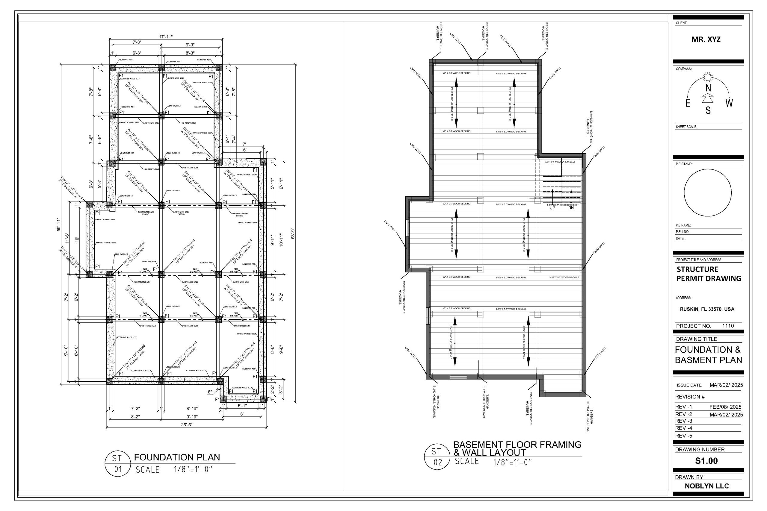
Foundation & Basement Framing Plan
The foundation is the most critical element of any structure, and our foundation drawings reflect that responsibility. Noblyn’s foundation plans show the complete layout of footings, grade beams, slab reinforcement, pier locations, and anchor bolt patterns — all dimensioned, detailed, and reinforced in accordance with geotechnical recommendations and IBC or IRC structural requirements. For projects with basements, we produce full basement framing plans showing retaining wall design, waterproofing specifications, and below-grade structural connections. Every foundation drawing is supported by a calculation package verifying bearing capacity, reinforcement sizing, and lateral soil pressure resistance — giving building department reviewers the engineering evidence they need to approve your foundation without question.
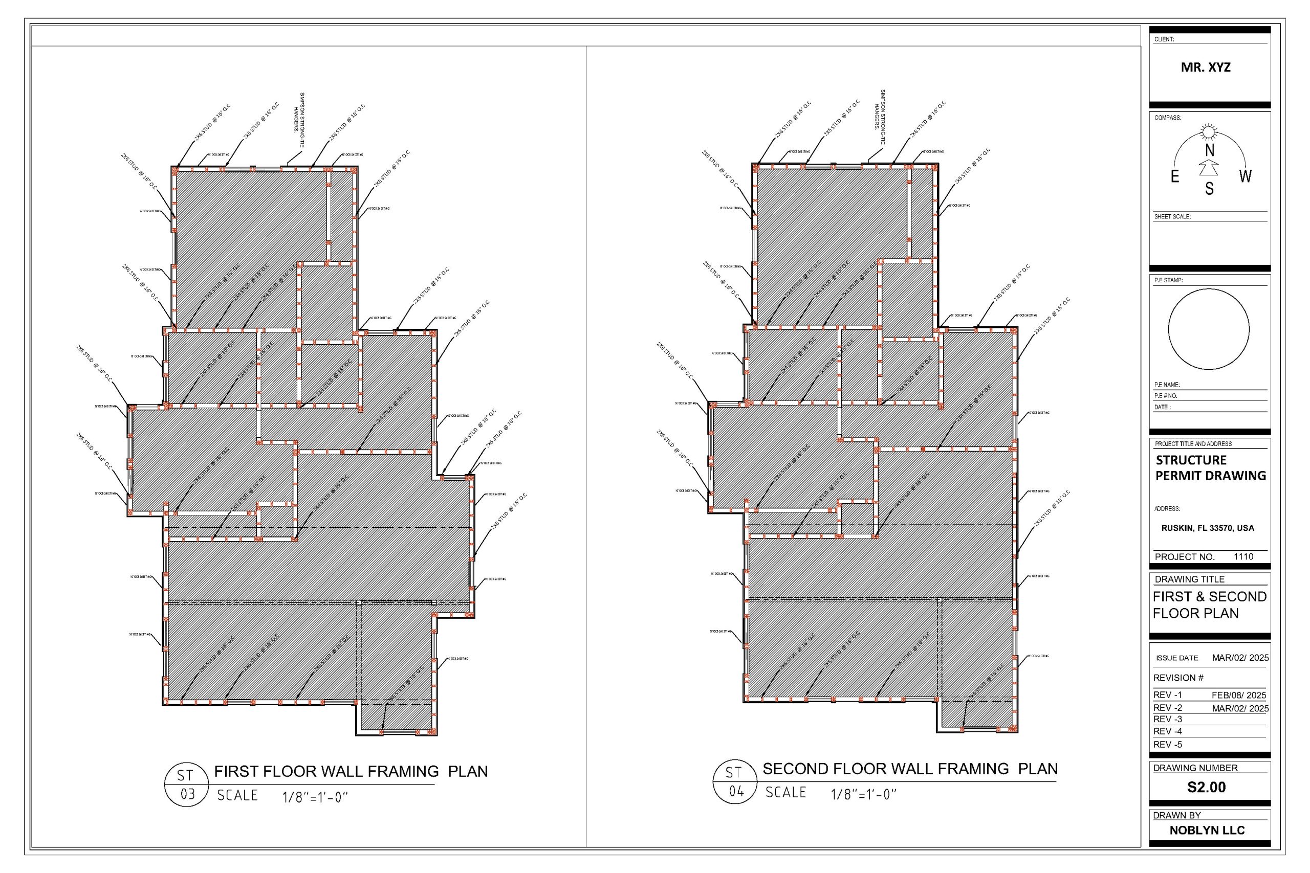
Floor Framing Plan
Our floor framing plans show the complete structural layout for every floor level of your building — joist directions and spacing, beam sizes and spans, post and column locations, floor penetrations, and all structural connections. Each member is sized based on calculated dead and live loads, and specified with the appropriate grade, species, and fastening requirements. Floor framing plans are coordinated directly with the architectural floor plan to ensure structural grids align with wall layouts and that all penetrations for MEP systems are structurally accounted for. The result is a floor structure that is efficient, safe, and straightforward for framers to build from without ambiguity or field-engineered guesswork.
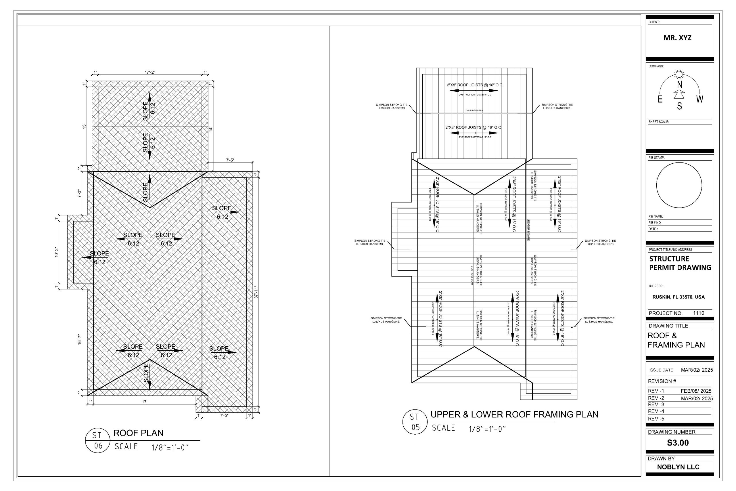
Roof and Framing Plan
Our roof and framing plans define the complete structural system above the top floor — whether that is a conventional rafter system, an engineered truss layout, a flat structural roof, or a hybrid combination. We show every ridge beam, valley rafter, hip member, and ceiling joist, with clear span dimensions and member sizes calculated for the governing load combination — including dead load, live load, wind uplift, and snow where applicable. Truss layouts are produced in coordination with the truss manufacturer’s engineering, and roof plans are cross-referenced with architectural roof plans to ensure structural geometry matches the design intent exactly. Uplift connections, ridge beam supports, and bearing wall requirements are all explicitly detailed to eliminate structural ambiguity at the framing stage.
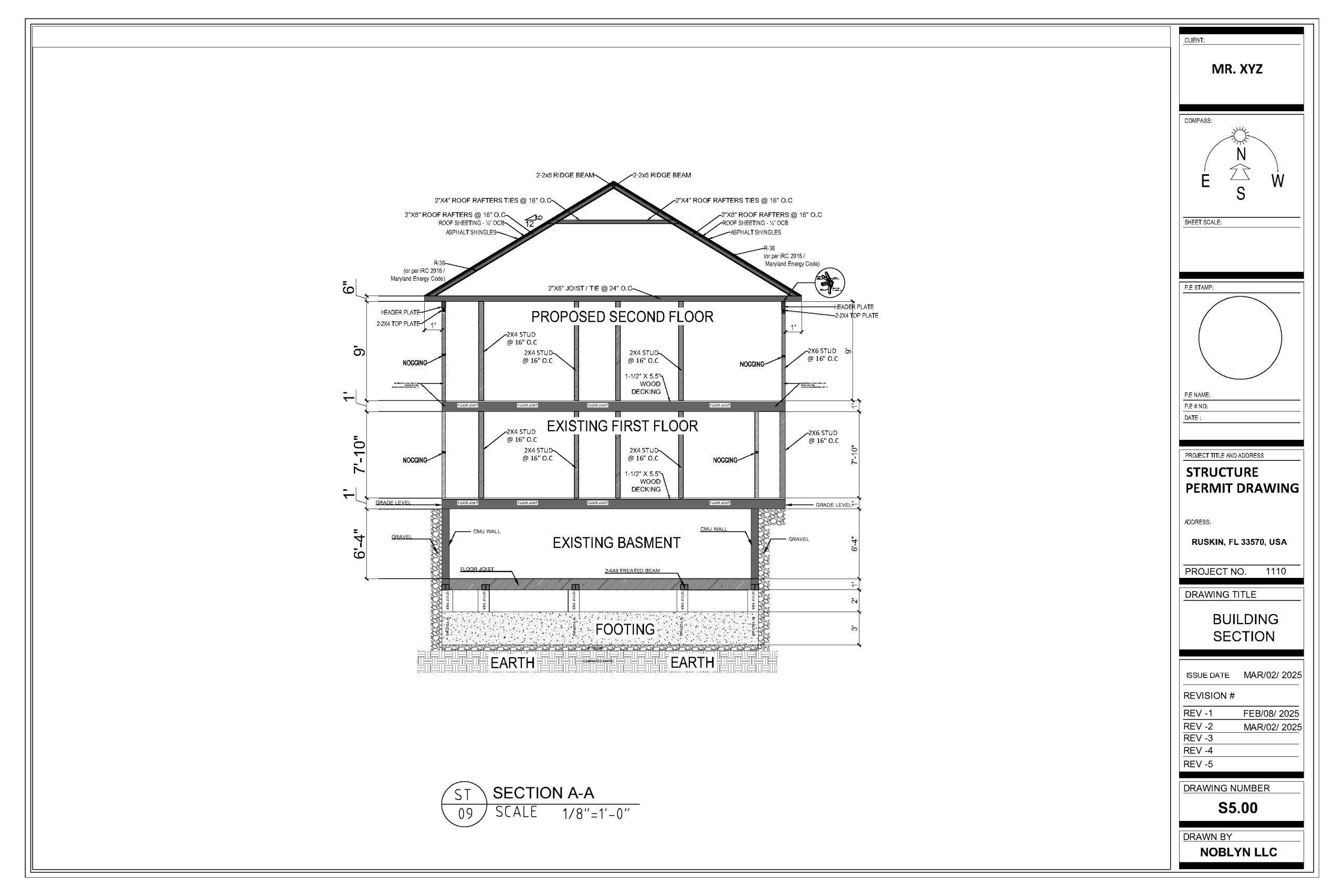
Building Section
Structural building sections cut vertically through the building to reveal the complete structural system from foundation to roof in a single view. Our sections show footing depth and reinforcement, floor-to-floor and floor-to-plate heights, beam and column sizes at each level, wall assembly types, and all critical structural connections. These sections are one of the most heavily reviewed documents in a structural permit submission — they allow plan reviewers and inspectors to verify that load paths are continuous from roof to foundation, that structural members are correctly sized at each level, and that the building will perform as a unified structural system under all design loads. Every section Noblyn produces is drawn to a scale that communicates structural intent with complete clarity.
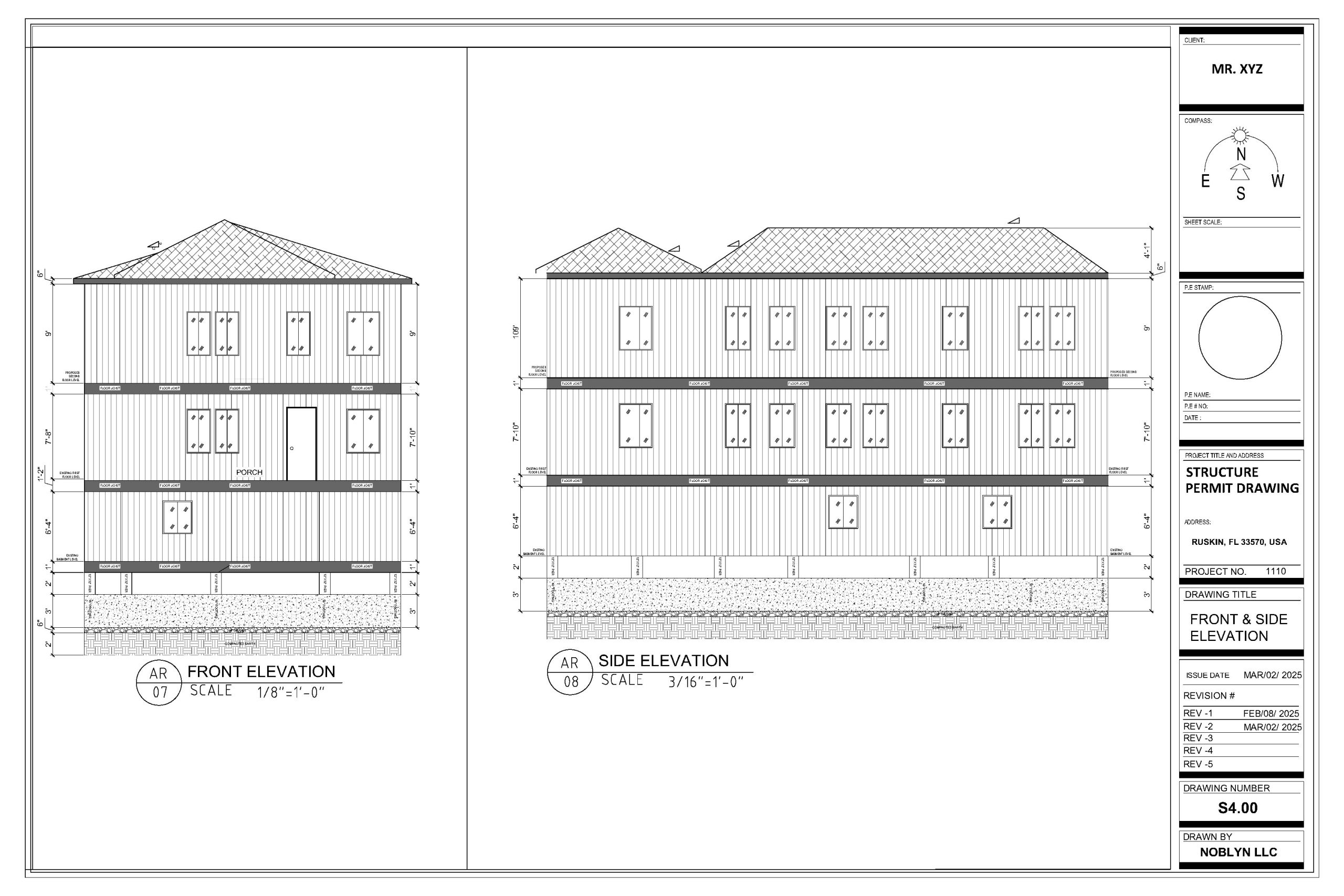
Exterior Elevation
Our structural exterior elevation drawings provide an additional layer of verification that the building’s structural system is consistent and correct from the outside in. Structural elevations show shear wall locations and lengths, hold-down anchor positions, moment frame locations, and lateral bracing elements — all clearly identified on each face of the building. These drawings are particularly important for buildings in high-wind or seismic zones, where lateral force resisting systems must be clearly documented and verified by plan review before a permit is issued. Structural elevations also confirm that wall height-to-thickness ratios comply with code slenderness limits and that all vertical load paths from roof to foundation are uninterrupted across every elevation.
Have Some Questions?
We Can Help!
A complete Noblyn structural package includes a foundation plan with footing and reinforcement details, floor framing plan for each level, roof and framing plan, structural building sections, structural exterior elevations, connection and detail sheets, and a full engineering calculation report covering dead, live, wind, seismic, and snow loads as applicable to your project and jurisdiction.
Yes — for virtually all new construction, additions, and significant structural modifications, building departments require a separate structural drawing set in addition to architectural plans. Architectural drawings show what the building will look like and how spaces are arranged. Structural drawings show how the building is engineered to stand safely — they are two separate and equally essential parts of a complete permit submission.