

There is a specific moment that happens in almost every project I have worked on over the past decade, and it usually arrives right after a client receives a plan check comment they do not understand. It reads something like “provide load path analysis for lateral force resisting system” or “submit calculations verifying beam adequate for tributary load,” and the homeowner or contractor calls us confused and, frankly, a little alarmed. If you have found yourself staring at a rejection letter full of structural engineering terminology with no idea what it actually means or why it matters, you are far from alone, and this is exactly the topic I want to walk through in plain language.
Structural drawings and load calculations are the part of a permit set that plan reviewers scrutinize most heavily, because they are the documents that prove your building will not fall down. Everything else in a permit set describes what the building looks like and how it functions. The structural package proves it is safe. After preparing structural documentation for hundreds of residential and commercial projects, I want to explain what these documents actually contain, why they are so often the source of permit delays, and what separates a structural package that sails through review from one that generates round after round of corrections.
Our team provides end-to-end architectural, structural, and MEP coordination to ensure your plans are compliant and ready for approval. Don’t let documentation delays hold you back.
Ready to turn your vision into a permit-ready project?
What Structural Drawings Actually Show
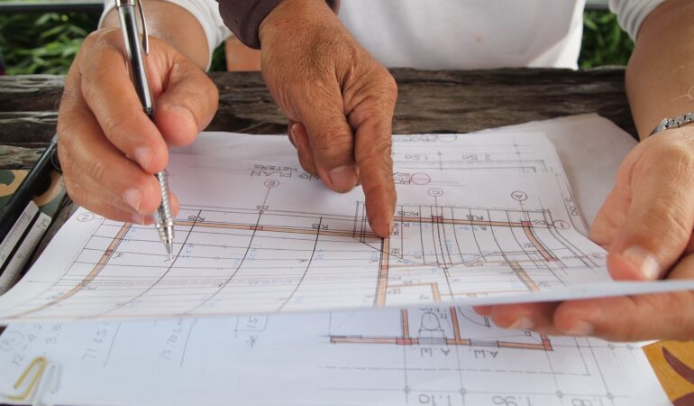
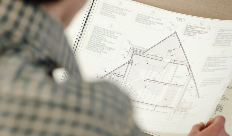
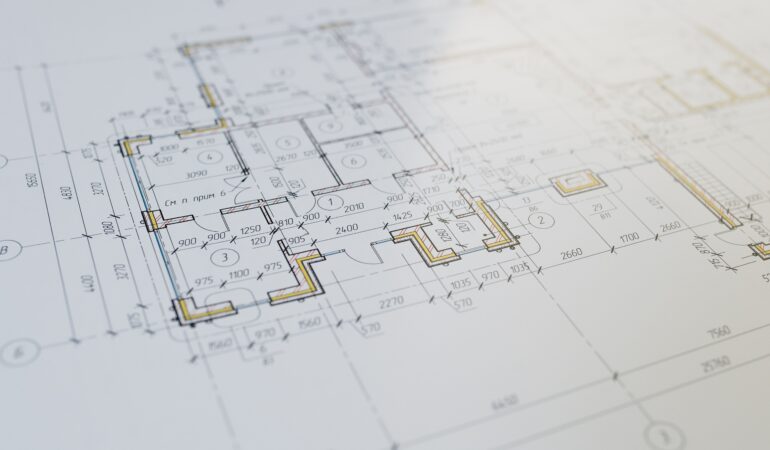
Structural drawings are a distinct set of documents from the architectural plans, even though they describe the same building. Where architectural drawings show room layouts, finishes, and how a space will be used, structural drawings show how the building physically holds itself up.
Foundation Plans
These show the size, depth, and reinforcement of footings, foundation walls, and slabs, calibrated to the soil bearing capacity at your specific site and the loads the foundation needs to support above it.
Framing Plans
Floor, wall, and roof framing plans identify every structural member, beams, joists, rafters, columns, and how they connect, along with sizes and spacing sufficient for a plan reviewer or contractor to build directly from the drawing.
Lateral System Details
In regions with meaningful wind or seismic exposure, drawings must show how the building resists horizontal forces, typically through shear walls, moment frames, or braced frames, along with the connections that tie these elements together and down to the foundation.
Connection Details
Some of the most scrutinized sheets in a structural set are the connection details, showing exactly how a beam attaches to a column, how a shear wall ties to the foundation, or how a ledger board attaches to an existing structure. Undersized or missing connection hardware is one of the most common sources of both plan check rejections and real world structural failures.
What Load Calculations Are and Why They Matter
Load calculations are the engineering math that proves every structural member shown on the drawings is adequately sized for the forces it will experience. This is not a formality. It is the technical justification a licensed structural engineer stamps and takes professional responsibility for.
Dead Load
The permanent weight of the building itself, including framing, roofing, flooring, and fixed mechanical equipment, calculated per square foot based on the actual materials specified.
Live Load
The variable weight a structure needs to accommodate during normal use, such as occupants, furniture, and stored materials, with minimum values set by code depending on the occupancy type. A rooftop deck, for example, requires a significantly higher live load allowance than a standard residential floor.
Wind Load
Calculated based on your region’s basic wind speed, exposure category, and building geometry, wind load calculations determine how much lateral and uplift force the structure must resist, which directly affects everything from roof connection hardware to shear wall requirements.
Seismic Load
In regions with meaningful seismic activity, calculations account for the building’s mass, height, and structural system to determine the lateral forces an earthquake could impose, driving decisions about shear wall placement and foundation anchorage.
Snow Load
In applicable climates, roof structures must be sized to carry the expected ground snow load adjusted for roof slope, exposure, and thermal factors specific to your jurisdiction.
The Insider Reality Most Homeowners and Contractors Never Hear
Here is something that surprises nearly every client during their first conversation with our structural team. The most common reason a structural submittal gets rejected is not an error in the math. It is a mismatch between the structural drawings and the architectural drawings. A beam sized correctly on the structural sheet but shown in a different location, or at a different depth, on the architectural reflected ceiling plan is exactly the kind of inconsistency that stops a plan reviewer cold, because now they cannot verify which document reflects the actual as built condition.
This is precisely why structural and architectural drawings prepared by a single coordinated team consistently move through review faster than sets assembled from separate, disconnected consultants. When the structural engineer and the architect are working from the same coordinated model, these conflicts get caught before submittal rather than after rejection.
Another mistake I see constantly, particularly on renovation and addition projects, is assuming that because an existing structure has stood for decades, no new calculations are required for a modification. Building departments almost universally require load calculations for any new structural work, including analysis of whether the existing structure can support new loads being introduced, such as a second story addition bearing on an original foundation that was never designed for it.
A third frequent issue involves tributary area miscalculations on beams supporting multiple framing members. A beam that looks adequately sized visually can still be underdesigned if the tributary area, meaning the portion of the building’s load that actually transfers through that specific member, was not calculated correctly. This is exactly the kind of error that a qualified structural engineer catches and a generalist drafter often misses.
Why Professional Structural Documentation Protects You Long After Permit Approval
Safety and Liability
A structural engineer’s stamp is not paperwork. It represents a licensed professional’s legal responsibility for the safety of the design. Cutting corners here exposes you to liability that far exceeds any upfront savings.
Fewer Field Conflicts During Construction
Coordinated structural drawings reduce the change orders and delays that occur when a framer discovers on site that a beam as drawn will not actually fit within the specified ceiling height or wall cavity.
Resale and Insurance Considerations
Structural work completed without proper permits and engineering, or work that later reveals coordination errors, frequently surfaces during real estate transactions and can complicate financing, insurance, or resale.
What to Look for in a Structural Drawing Partner
Confirm your structural engineer is licensed in your specific state and has experience with your jurisdiction’s adopted code edition and local amendments.
Ask whether structural and architectural drawings are produced under one coordinated process or handled by entirely separate parties, since this single factor most often determines whether your submittal is internally consistent.
Confirm load calculations account for your actual site conditions, including soil bearing capacity, local wind exposure category, and applicable seismic design category, rather than generic assumptions.
Ask whether revisions are included if the building department requests clarification or additional analysis, since correction letters on structural submittals are common even for well prepared sets.
Final Thoughts From the Drafting Table
Structural drawings and load calculations are, in my professional opinion, the single most important documents in your entire permit set. They are the technical proof that your building is safe, and they are also, statistically, the documents most likely to generate plan check corrections when prepared without proper coordination. Investing in a structural package produced alongside your architectural drawings by a team that understands both disciplines is consistently the fastest path to permit approval and the safest path for everyone who will eventually occupy the building.
If you need structural drawings and load calculations prepared as part of a fully coordinated permit set, we would be glad to review your project and provide a free quote within twenty four hours.
Our team provides end-to-end architectural, structural, and MEP coordination to ensure your plans are compliant and ready for approval. Don’t let documentation delays hold you back.
Ready to turn your vision into a permit-ready project?

Fayaz
Frequently Asked Question - FAQs
Architectural drawings show how a building looks and functions, including room layouts and finishes, while structural drawings show how the building physically supports itself, including framing, foundations, and load bearing connections.
In most jurisdictions, yes. Building departments typically require load calculations for any new structural work, including verification that existing structural elements can support new loads introduced by the renovation.
A licensed structural engineer, registered in the state where the project is located, must prepare and stamp structural drawings and calculations, taking professional responsibility for the design.
The most common reason is a coordination conflict between the structural and architectural drawings, such as a beam or wall shown differently on each set, which prevents the reviewer from verifying an internally consistent design.
Timelines vary based on project complexity and lateral system requirements, but structural drawings prepared alongside coordinated architectural documents typically take a few weeks, with additional time allotted for any plan check revisions.