
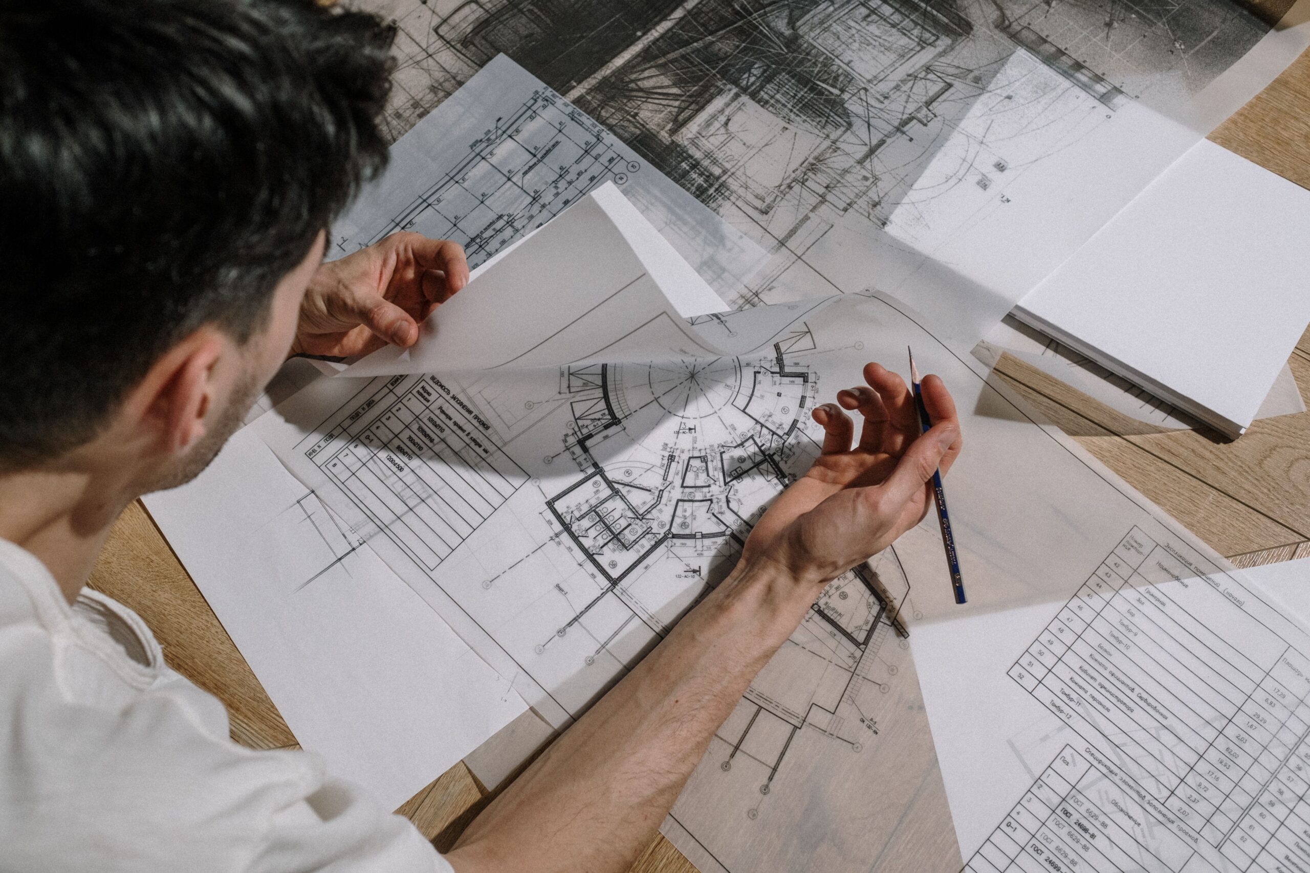
If you have managed more than a handful of ground up projects, you have almost certainly experienced this exact frustration. The site plan comes from one consultant, the grading and drainage plan comes from another, and the utility connection details show up separately from a third source, and somewhere in that fragmented process, the invert elevation on the drainage plan does not quite match the finished floor elevation on the site plan, or the proposed utility trench conflicts with a grading contour that was never updated after the last revision. Now you are the one stuck reconciling three documents that should have agreed with each other from the start, usually while a plan reviewer is asking questions you cannot fully answer because you did not produce any of the underlying calculations yourself.
After a decade producing civil documentation for contractors managing everything from single lot residential projects to larger commercial developments, I want to walk through why civil drawings so often become the most fragmented, and therefore the most delay prone, part of a permit set, and why having site plans, utility drawings, and grading documentation produced as one coordinated package changes the outcome for contractors managing tight schedules.
Our team provides end-to-end architectural, structural, and MEP coordination to ensure your plans are compliant and ready for approval. Don’t let documentation delays hold you back.
Ready to turn your vision into a permit-ready project?
What a Complete Civil Drawing Package Actually Covers
Civil drawings describe how a building interacts with the land it sits on and the infrastructure surrounding it. Unlike architectural or structural drawings, which largely describe the building itself, civil drawings describe everything happening at and below the surface of the site.
Site Plans
Showing property boundaries, setbacks, existing and proposed structures, parking, access points, and easements, the site plan is typically the first document a plan reviewer checks against zoning requirements, and it needs to align precisely with every other civil sheet in the set.
Grading and Drainage Plans
Documenting existing and proposed elevations across the site, grading plans establish how stormwater will move across the property, directing runoff away from structures and toward approved discharge points while meeting the jurisdiction’s requirements for retention, detention, or infiltration depending on local stormwater management rules.
Utility Plans
Showing proposed water, sewer, electrical, gas, and telecommunications connections, including pipe sizing, invert elevations, and connection points to existing municipal infrastructure, utility plans need to be coordinated with both the grading plan, since utility trenches affect site elevations, and the building’s mechanical and plumbing drawings, since service connections need to align with where those systems actually enter the structure.
Erosion and Sediment Control Plans
Required in most jurisdictions during construction, these plans document temporary measures, such as silt fencing and construction entrances, that prevent sediment from leaving the site during earthwork and construction activities.
Why Civil Drawings Are So Often the Most Fragmented Part of a Permit Set
Civil work sits at an unusual intersection. It requires licensed civil engineering for grading, drainage, and utility design, but it also needs to be tightly coordinated with the architectural building footprint and the structural foundation design. In many project delivery structures, civil drawings are sourced from a separate consultant entirely, often a surveyor or civil firm with no direct connection to the team producing the architectural and structural drawings, which is precisely where coordination breaks down.
Elevation Mismatches
One of the most common issues I encounter is a finished floor elevation shown on the architectural plans that does not match the elevation the grading plan was actually designed around, sometimes because the grading plan was finalized before a late stage architectural revision and never updated afterward.
Utility Trench and Foundation Conflicts
Proposed utility trenches, particularly for sewer laterals with specific slope requirements, sometimes conflict with foundation footprints or footing depths that were finalized independently, a conflict that is far cheaper to catch on paper than to discover once excavation has begun.
Drainage Assumptions That Do Not Match As Built Grading
Grading plans calculating stormwater flow based on assumed contours that differ from the actual site topography, because the topographic survey used was outdated or the site experienced grading changes between survey and design, is a surprisingly common source of both plan check rejection and, worse, actual drainage problems after construction.
The Insider Reality Contractors Rarely Hear Until It Costs Them Time
Here is something that becomes obvious after enough projects but rarely gets explained upfront. The civil engineering work on a project is almost never the part that takes the longest to produce. It is the coordination between civil, architectural, and structural drawings, particularly around finished floor elevations, utility entry points, and foundation depths, that determines whether your permit submittal moves cleanly or bounces back with corrections that require multiple consultants to jointly resolve.
The most common and costly mistake I see contractors run into is discovering a civil coordination conflict only after being awarded the project and mobilizing crews, because the civil drawings were produced early in the entitlement process by a different firm than the one who later finalized the architectural and structural design, and nobody circled back to confirm the documents still agreed with each other by the time construction drawings were complete.
Another frequent issue involves utility connection points that were approved on paper but never actually field verified against existing municipal infrastructure. A sewer lateral connection shown at a specific invert elevation on the utility plan needs to actually be achievable given the depth and location of the existing municipal main, and I have seen projects where this was not confirmed until a contractor’s crew was already in the trench, resulting in a redesign that stalled the schedule at the most expensive possible point in the process.
A third issue that catches contractors off guard on infill and urban sites involves stormwater management requirements that exceed what a generic grading plan template accounts for. Many jurisdictions now require detailed hydrology calculations demonstrating post construction runoff does not exceed pre construction rates, and a civil package that treats this as a formality rather than an actual engineering exercise specific to your site is one of the more common sources of extended plan check timelines on commercial and multifamily projects.
How a Coordinated Civil Package Protects Contractor Timelines
Consistent Elevations Across Every Discipline
When site plans, grading plans, and utility plans are produced alongside the architectural and structural drawings rather than sourced independently, finished floor elevations, foundation depths, and drainage patterns are checked against each other before submittal, not discovered to be in conflict after.
Verified Utility Connections Before Construction
A coordinated civil team confirms proposed utility connections against actual municipal infrastructure records during design, rather than leaving that verification to happen in the field once excavation is already underway.
Fewer Plan Check Rounds Requiring Multiple Consultants
When a civil correction letter requires input from architectural, structural, and civil disciplines simultaneously, resolving it takes considerably longer if those three parties have never worked together before. A single coordinated team resolves these corrections far faster because the working relationship and shared context already exist.
More Accurate Bidding and Scheduling
Contractors bidding earthwork, utility installation, and foundation work from a coordinated civil set can price and schedule with confidence, since the documents reflect a design that has already been checked for internal consistency rather than one that may still contain unresolved conflicts.
What to Look for When Sourcing Civil Drawings for Your Projects
Confirm the civil engineer is licensed in your project’s specific state and familiar with the local jurisdiction’s stormwater management and grading requirements.
Ask whether civil drawings are produced in coordination with the architectural and structural team, or sourced as an entirely separate process, since this is the single biggest factor in whether elevations and utility connections actually agree across every discipline.
Confirm utility connection points have been checked against actual municipal infrastructure records rather than assumed from general area information.
Ask whether revisions are included if plan check corrections require coordinated input across civil, architectural, and structural disciplines, since these multi discipline corrections are among the most time consuming to resolve when the original team was fragmented.
Final Thoughts From the Drafting Table
Civil drawings determine far more about a project’s schedule and cost than most contractors expect going in, precisely because they sit at the intersection of engineering disciplines that are too often sourced from disconnected consultants. A site plan, grading and drainage plan, and utility plan produced as one coordinated package, checked against the architectural and structural design rather than assembled independently, is consistently the most reliable way to avoid the elevation mismatches, utility conflicts, and drainage surprises that stall projects at their most expensive moments.
If you are managing project timelines and need site plans, utility drawings, and grading documentation prepared as part of a fully coordinated permit package, we would be glad to review your project and provide a free quote within twenty four hours.
Our team provides end-to-end architectural, structural, and MEP coordination to ensure your plans are compliant and ready for approval. Don’t let documentation delays hold you back.
Ready to turn your vision into a permit-ready project?

Taswar Hussain
Frequently Asked Question - FAQs
A complete package typically includes a site plan showing property boundaries and setbacks, a grading and drainage plan documenting stormwater management, utility plans for water, sewer, and other service connections, and an erosion and sediment control plan for the construction period.
Civil drawings are frequently produced by a separate consultant working independently from the architectural and structural team, which makes elevation mismatches and utility routing conflicts common unless the disciplines are actively coordinated with one another.
Utility connection points shown on the civil drawings should be verified against actual municipal infrastructure records during the design phase, rather than confirmed for the first time once a crew is already in the trench.
Requirements vary by jurisdiction, but many municipalities now require calculations demonstrating that post construction stormwater runoff does not exceed pre construction rates, particularly on commercial, multifamily, or larger infill sites.
Timelines depend on site complexity and jurisdiction requirements, but a coordinated site plan, grading plan, and utility package produced alongside architectural and structural drawings typically takes a few weeks, with additional time reserved for jurisdictional review.